1. Εισαγωγή
This manual provides comprehensive instructions for the AYWHP ESP-32-S3 Development Board, equipped with the ESP-1-N16R8 module. This high-performance platform is designed for AIoT and Arduino enthusiasts, integrating a low-power MCU System-on-Chip (SoC) with 2.4 GHz Wi-Fi and Bluetooth LE dual-mode wireless communication.
Τα βασικά χαρακτηριστικά περιλαμβάνουν:
- Low-power performance: Integrates 2.4 GHz Wi-Fi and Bluetooth 5 (LE) dual-mode communication, ideal for Internet of Things (IoT) projects.
- Simple programming and debugging: Facilitates programming via dual USB Type-C ports, supporting both USB and UART modes.
- Multiple Power Saving Modes: Configurable low-power modes for extended battery life in various application scenarios.
- Dual download modes: Supports both USB direct connection and USB to serial port download for enhanced flexibility.
- Diverse connectivity options: Dual-mode Wi-Fi and Bluetooth 5.0 (LE) connectivity for a wide range of smart devices.
2. Το προϊόν τελείωσεview
The AYWHP ESP-32-S3 Development Board is designed for ease of use and versatility. Below are detailed views of the board's components and pinout.
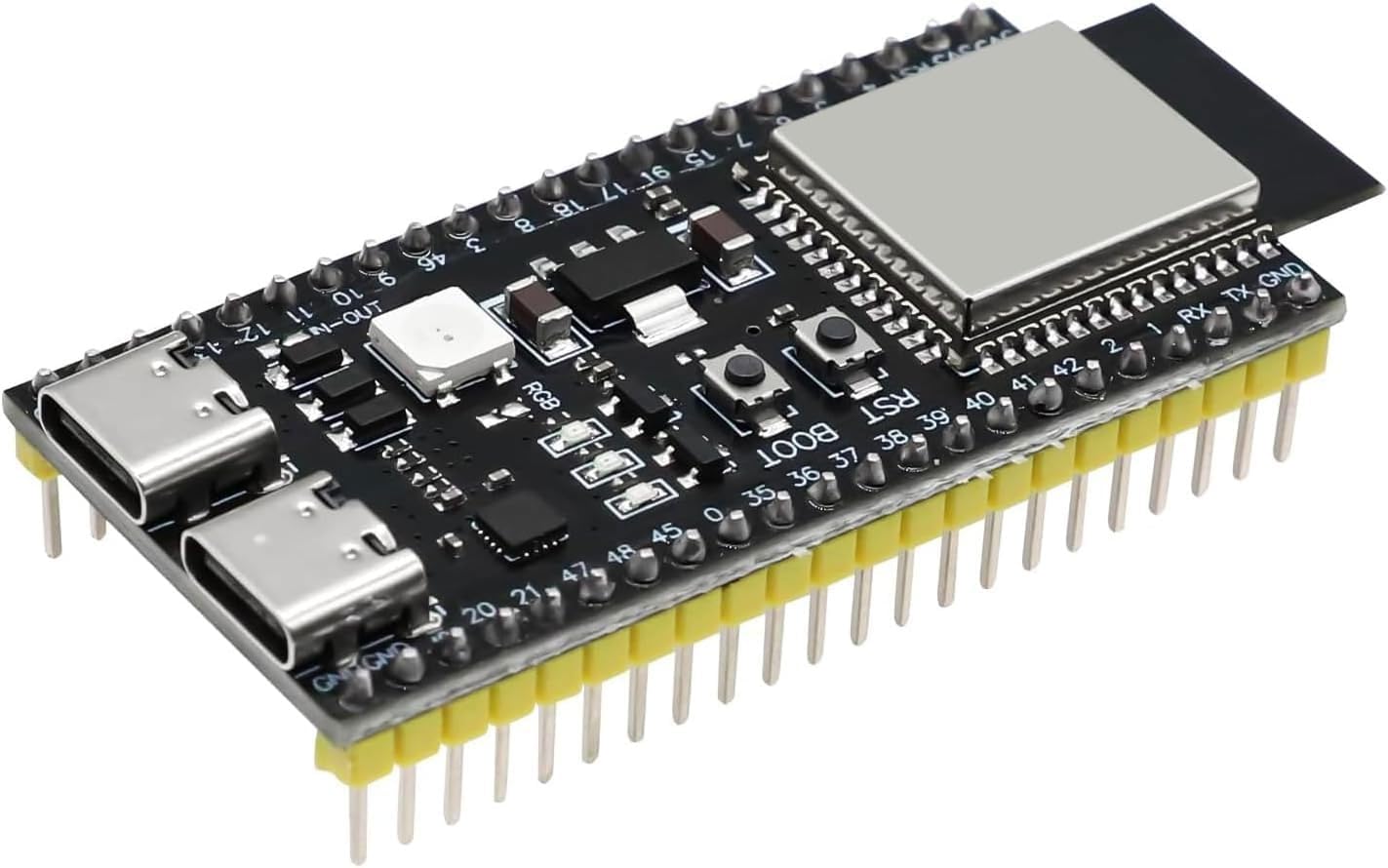
Εικόνα 2.1: Κορυφή view of the AYWHP ESP-32-S3 Development Board, showing the ESP-1-N16R8 module, USB-C ports, and pin headers.
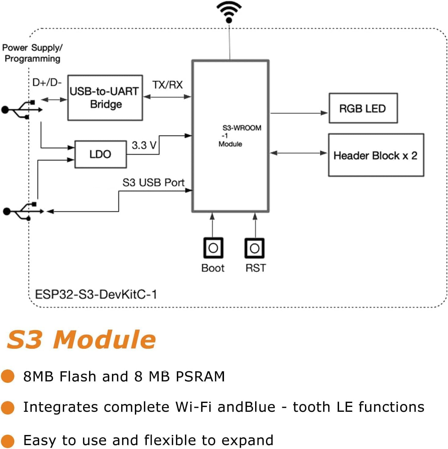
Εικόνα 2.2: Block diagram illustrating the internal connections and components of the ESP32-S3-DevKitC-1, including the S3-WROOM-1 module, USB-to-UART Bridge, LDO, RGB LED, and header blocks.
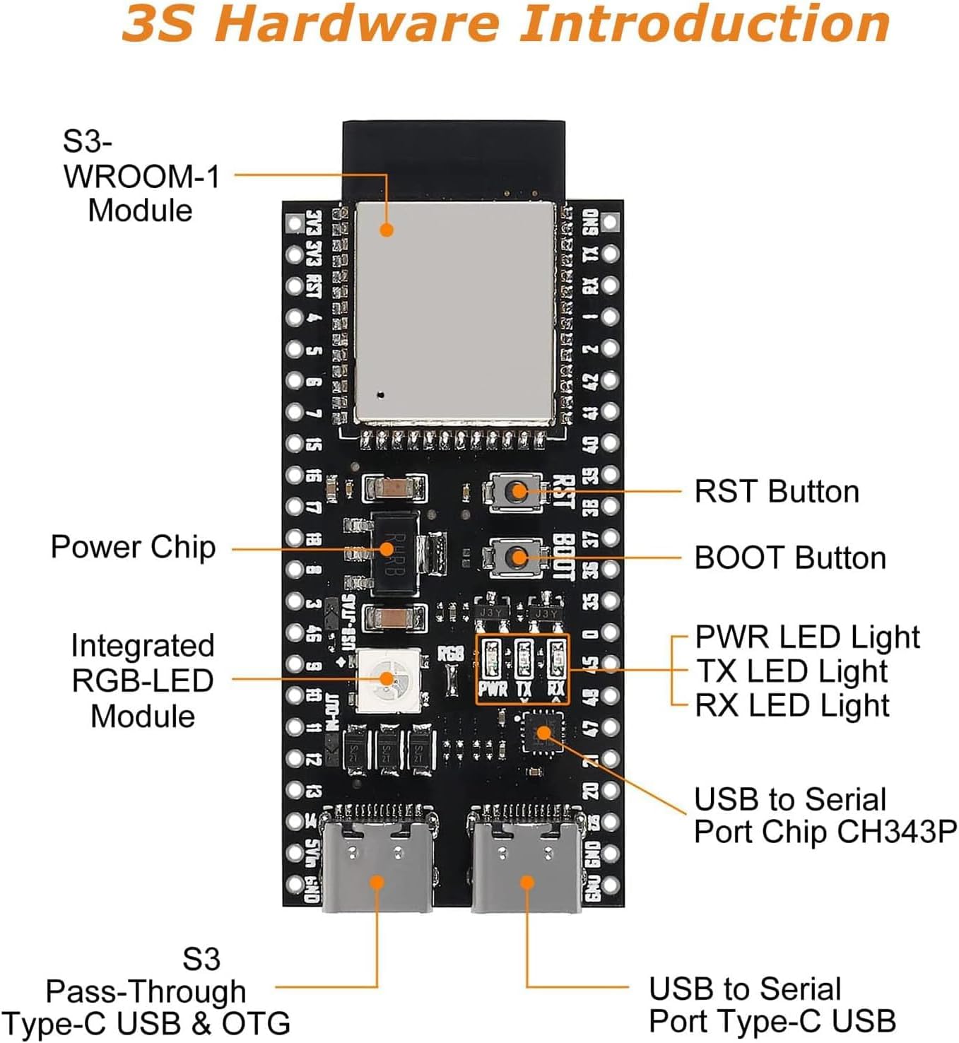
Εικόνα 2.3: Detailed hardware overview of the ESP32-S3 board, highlighting key components such as the S3-WROOM-1 Module, RST Button, BOOT Button, PWR LED, TX LED, RX LED, Integrated RGB-LED Module, USB to Serial Port Chip (CH343P), and S3 Pass-Through Type-C USB & OTG port.

Εικόνα 2.4: Pinout diagram for the ESP32-S3-DevKitM-1 module, detailing GPIO assignments, power pins (3V3, 5V, GND), and special functions like JTAG, ADC, Touch, Serial, and RTC pins.
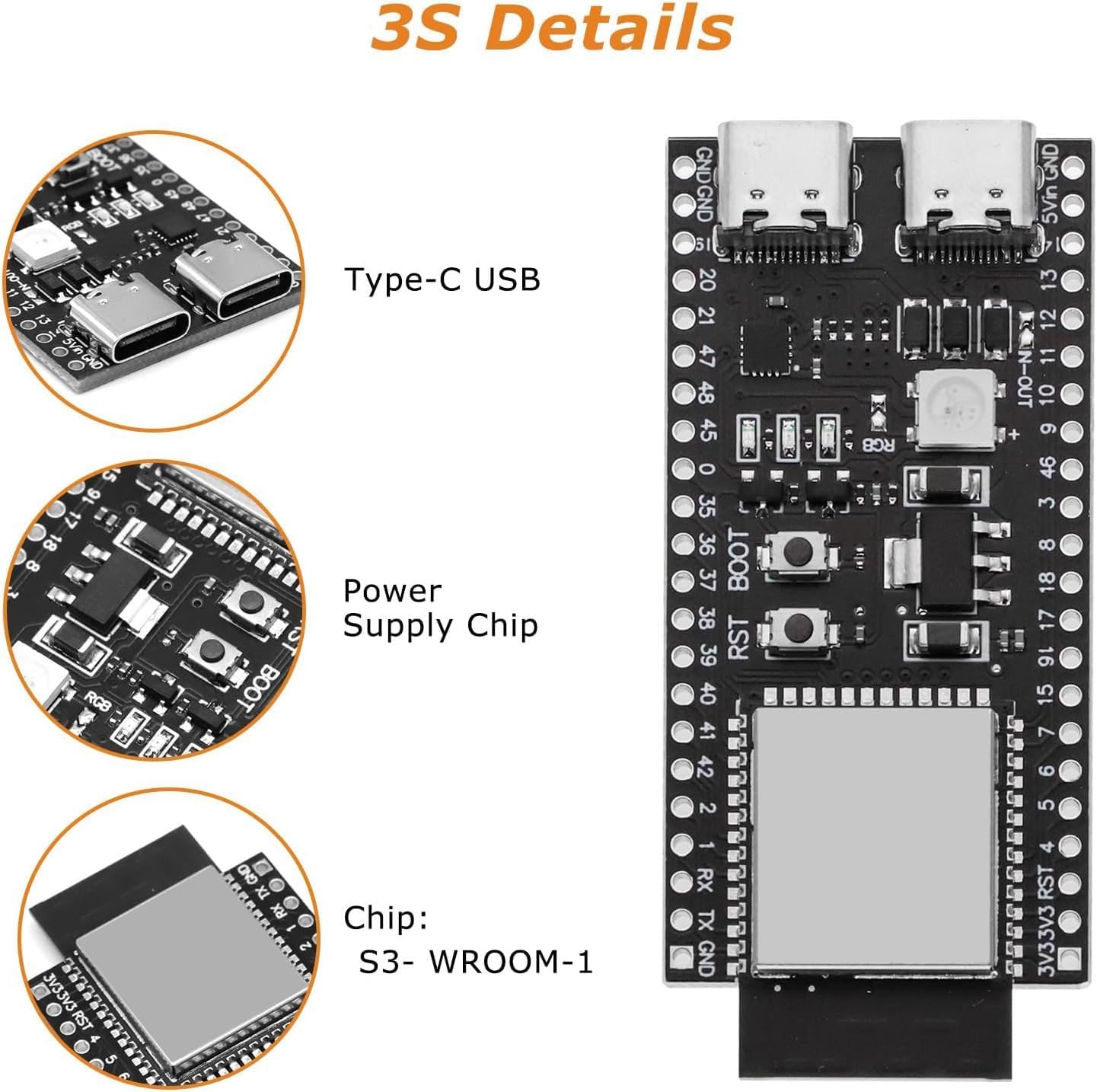
Εικόνα 2.5: Κοντινό πλάνο views of critical components on the ESP32-S3 board, including the Type-C USB ports, the Power Supply Chip, and the S3-WROOM-1 module.

Εικόνα 2.6: Dimensional drawing of the ESP32-S3 Development Board, showing measurements in millimeters and inches for physical integration.

Εικόνα 2.7: Μπροστά και πίσω views of the ESP32-S3 Development Board, illustrating component placement on both sides and pin labels.
3. Προδιαγραφές
| Χαρακτηριστικό | Λεπτομέρεια |
|---|---|
| Μικροελεγκτές | ESP32-S3 |
| Τσιπ | ESP-1-N16R8 |
| CPU | Διπύρηνος επεξεργαστής Xtensa 32-bit LX7 |
| Ταχύτητα ρολογιού | Έως 240 MHz |
| Flash Memory | 16 MB (embedded) |
| ΕΜΒΟΛΟ | 512 KB |
| Ασύρματη Συνδεσιμότητα | Wi-Fi 802.11 b/g/n, Bluetooth 5.0 (LE) |
| I/O Pins | 34 GPIO |
| Μετατροπέας αναλογικού σε ψηφιακό (ADC) | 12-bit resolution, 18 channels |
| Digital-to-Analog Converter (DAC) | Ανάλυση 8 bit |
| Διεπαφές UART | 3 |
| Διεπαφές SPI | 2 |
| Διεπαφές I2C | 2 |
| Κανάλια PWM | 16 |
| Λειτουργικός τόμοςtage | 3.3V |
| Τροφοδοτικό | USB-C or external 5V supply |
| Διασύνδεση USB | USB-UART bridge for programming and debugging |
| Αριθμός μοντέλου είδους | YY1-0163 |
| Λειτουργικό σύστημα | Arduino Bootloader |
4. Οδηγίες εγκατάστασης
Follow these steps to set up your AYWHP ESP-32-S3 Development Board for programming.
- Εγκατάσταση προγραμμάτων οδήγησης: Ensure you have the necessary USB-to-UART bridge drivers installed on your computer. Common drivers include CP210x and CH340/341. Without these, your computer may not recognize the board.
- Install Arduino IDE or PlatformIO: Download and install your preferred development environment. The board is compatible with Arduino IDE and PlatformIO (e.g., within VSCode).
- Add ESP32-S3 Board Support:
- For Arduino IDE: Go to File > Προτιμήσεις, add the ESP32 board manager URL (συνήθως
https://raw.githubusercontent.com/espressif/arduino-esp32/gh-pages/package_esp32_index.json) to "Additional Board Manager URLs". Then, go to Εργαλεία > Πίνακας > Διαχειριστής πίνακα, search for "ESP32", and install the latest version. - For PlatformIO: Ensure the Espressif 32 platform is installed.
- For Arduino IDE: Go to File > Προτιμήσεις, add the ESP32 board manager URL (συνήθως
- Συνδέστε την πλακέτα: Connect the ESP-32-S3 board to your computer using a USB Type-C cable. Use the Θύρα USB for direct programming and debugging, not necessarily the COM port, as some users report issues with the latter for code uploads.
- Επιλέξτε πλακέτα και θύρα: In your IDE, select the correct board (e.g., "ESP32S3 Dev Module" or similar) and the corresponding COM port (Windows) or
/dev/cu.usbserial-XXXX(macOS). - Enable USB CDC on Boot (Optional but Recommended): If you intend to use the direct USB port for serial communication, enable "USB CDC on Boot" in your board settings within the IDE. This allows the board to appear as a serial port directly over the USB connection.
5. Οδηγίες λειτουργίας
Once your development environment is set up, you can begin programming and operating your ESP-32-S3 board.
- Κωδικός μεταφόρτωσης: Write your code (sketch) in the Arduino IDE or PlatformIO. Click the "Upload" button to compile and transfer the code to the board. If uploading fails, ensure the correct port and board are selected. You may need to press and hold the Κουμπί ΕΚΚΙΝΗΣΗΣ while pressing and releasinζ το Κουμπί RST, then release BOOT to enter download mode, though some configurations allow direct upload.
- Serial Monitor: Use the Serial Monitor in your IDE to view output from your board (e.g., debug messages, sensor readings). Ensure the baud rate matches the one specified in your code (e.g., 115200).
- Wi-Fi και Bluetooth: Utilize the integrated Wi-Fi and Bluetooth 5.0 (LE) capabilities by including the appropriate libraries in your code (e.g.,
WiFi.h,BluetoothSerial.h). - Χρήση GPIO: Refer to the pinout diagram (Figure 2.4) for correct GPIO assignments when connecting external components.
- RGB LED: The onboard RGB LED is typically connected to GPIO48. To activate it, ensure any necessary jumpers are closed or configured in your code.
6. Συντήρηση
Proper care ensures the longevity and reliable operation of your development board.
- Αποθήκευση: Αποθηκεύστε την πλακέτα σε ξηρό, αντιστατικό περιβάλλον όταν δεν τη χρησιμοποιείτε.
- Καθάρισμα: Use a soft, dry brush or compressed air to remove dust. Avoid liquids.
- Χειριζόμενος: Handle the board by its edges to avoid touching components, especially the pins, which can be sensitive to static discharge.
- Τροφοδοτικό: Always use a stable 5V power supply via the USB-C port or external pins. Avoid over-voltage.
7. Αντιμετώπιση Προβλημάτων
Ακολουθούν λύσεις για συνηθισμένα προβλήματα που ενδέχεται να αντιμετωπίσετε:
- Η πλακέτα δεν αναγνωρίζεται από τον υπολογιστή:
- Διάλυμα: Install or update the correct USB-to-UART bridge drivers (CP210x, CH340/341). Try a different USB cable or port on your computer.
- Code Upload Fails:
- Διάλυμα: Ensure the correct board and COM/USB port are selected in your IDE. Try manually putting the board into download mode: press and hold the Κουμπί ΕΚΚΙΝΗΣΗΣ, then briefly press and release the Κουμπί RST, then release the BOOT button. Ensure you are using the correct USB port for programming (often labeled "USB" or "OTG" rather than "UART").
- Διάλυμα: Verify your code compiles without errors. Check for correct board settings in your IDE, especially flash size and partition scheme.
- RGB LED Not Lighting Up:
- Διάλυμα: The RGB LED is typically on GPIO48. Ensure your code targets this pin. Some boards may require a jumper connection to be closed for the RGB LED to function; inspect your board for such a jumper.
- Προβλήματα συνδεσιμότητας Wi-Fi/Bluetooth:
- Διάλυμα: Check your code for correct Wi-Fi/Bluetooth initialization and credentials. Ensure the antenna is not obstructed. In rare cases, a faulty antenna connection on the board might be the cause.
- Board is Completely Unresponsive:
- Διάλυμα: Verify the power supply. Try a different USB cable and port. If possible, test with another board to rule out software or PC-related issues.
8. Τι υπάρχει στο κουτί
Το πακέτο περιλαμβάνει:
- 1 X AYWHP ESP32-S3 Development Board with ESP-1-N16R8 module
9. Εγγύηση και υποστήριξη
For technical support or warranty inquiries, please contact your retailer or the manufacturer directly. Keep your purchase receipt for warranty claims. General support resources for ESP32-S3 development are widely available online through community forums and Espressif documentation.


