1. Εισαγωγή
This manual provides comprehensive instructions for the safe and effective use of the Generic 5-90V DC Digital Automotive Circuit Tester. This versatile tool is designed for precise voltage detection, continuity testing, and fuse diagnostics in various automotive and marine electrical systems.
Βασικά Χαρακτηριστικά:
- Precise Voltage Ανίχνευση: Accurately displays voltage readings from 5V to 90V DC, suitable for automotive, RV, and fuse testing.
- Durable Design with LED Indicator: Equipped with a high-brightness LED indicator, stainless steel probes, and an extended spring-loaded cable for durability and access in confined areas.
- Πολυλειτουργική χρήση: Functions as a circuit tester, voltage detector, and fuse tester for various vehicles including cars, trucks, and marine vessels.
- Ασφαλές και φιλικό προς το χρήστη: Designed with a clear digital display and ergonomic grip for convenient operation.
- Συμπεριλαμβανόμενα αξεσουάρ: Comes with sturdy probes and connecting cables, compatible with 12V/24V systems for automotive electrical inspections and DIY projects.
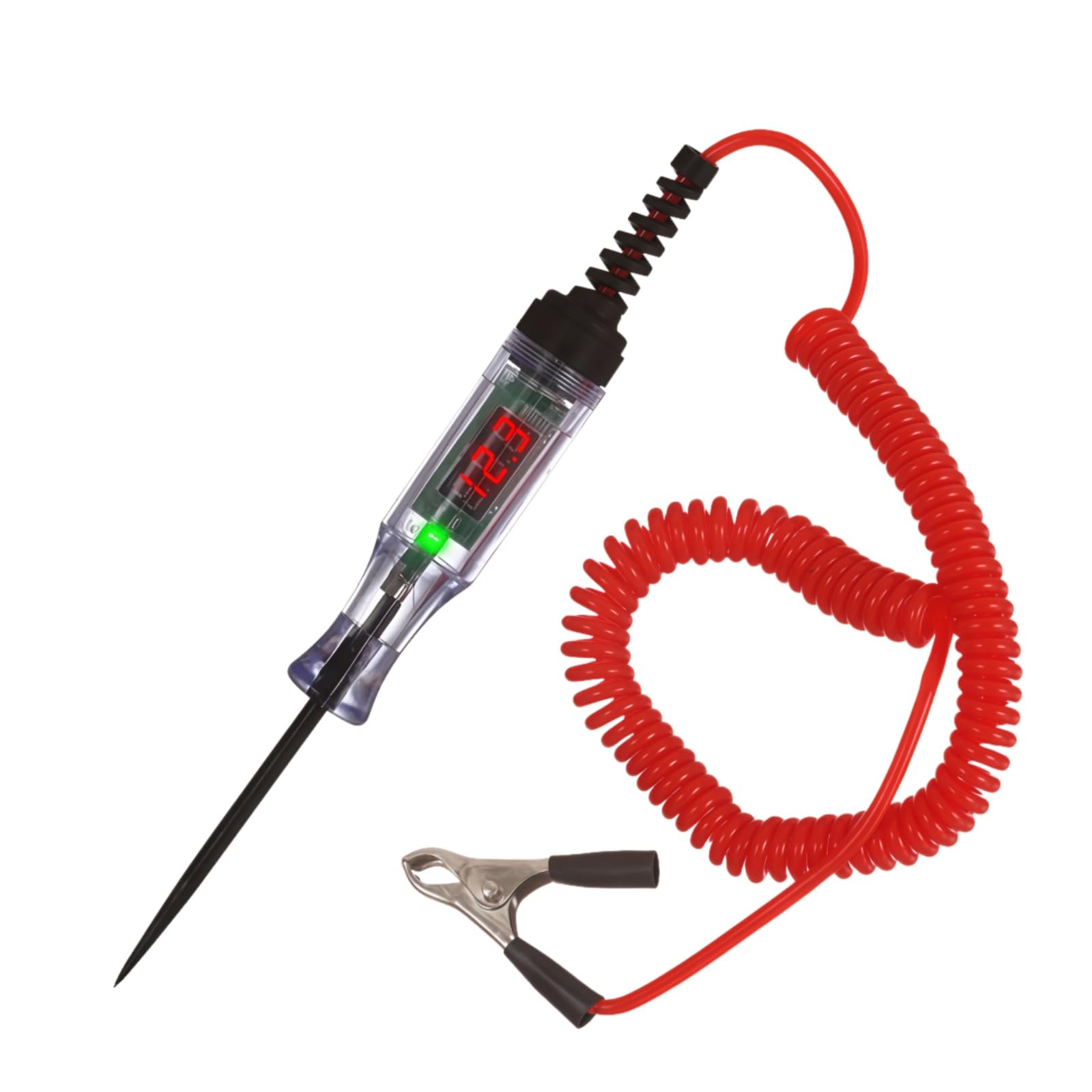
Figure 1.1: Generic 5-90V DC Digital Automotive Circuit Tester.
2. Πληροφορίες Ασφάλειας
Always observe the following safety precautions to prevent injury or damage to the device or vehicle:
- Να φοράτε κατάλληλο ατομικό προστατευτικό εξοπλισμό, συμπεριλαμβανομένων γυαλιών ασφαλείας.
- Do not use the tester on circuits exceeding 90V DC.
- Ensure proper grounding of the alligator clip before probing live circuits.
- Keep the probe tip away from moving parts or hot surfaces.
- Do not attempt to repair or modify the tester. Refer to qualified personnel for service.
3. Συστατικά προϊόντος
The Automotive Circuit Tester consists of the following main components:
- Ψηφιακή οθόνη: Εμφανίζει τόμtagαναγνώσεις.
- Ένδειξη LED: Provides visual feedback on circuit status.
- Αισθητήρας από ανοξείδωτο χάλυβα: Sharp tip for piercing wires or contacting terminals.
- Extended Spring Wire: Flexible coiled cable for reach and tangle-free use.
- Κλιπ αλιγάτορα: For secure connection to ground or power sources.

Figure 3.1: Labeled components of the Automotive Circuit Tester, including the LED digital display, indicator light, probe, alligator clips, and extended spring wire.

Figure 3.2: Dimensions of the Automotive Circuit Tester, showing the probe length (7.24 inches), overall length (9.6 inches), and alligator clip length (2.08 inches).
4. Ρύθμιση
- Συνδέστε το κλιπ Alligator: Securely attach the alligator clip to a known good ground point on the vehicle chassis or the negative terminal of the battery. Ensure a clean, solid connection for accurate readings.
- Prepare the Probe: Remove the protective cover from the stainless steel probe tip.
5. Οδηγίες λειτουργίας
5.1. Τομtage Δοκιμή
- Ensure the alligator clip is securely grounded.
- Carefully touch the probe tip to the circuit or component you wish to test.
- Η ψηφιακή οθόνη θα εμφανίσει την έντασηtage reading. The LED indicator will illuminate (red for positive, green for negative) to indicate polarity.
- Αν ο τόμtage exceeds the tester's maximum capacity (90V DC), the display may show an error or an "H" indicating high voltage. Disconnect immediately.
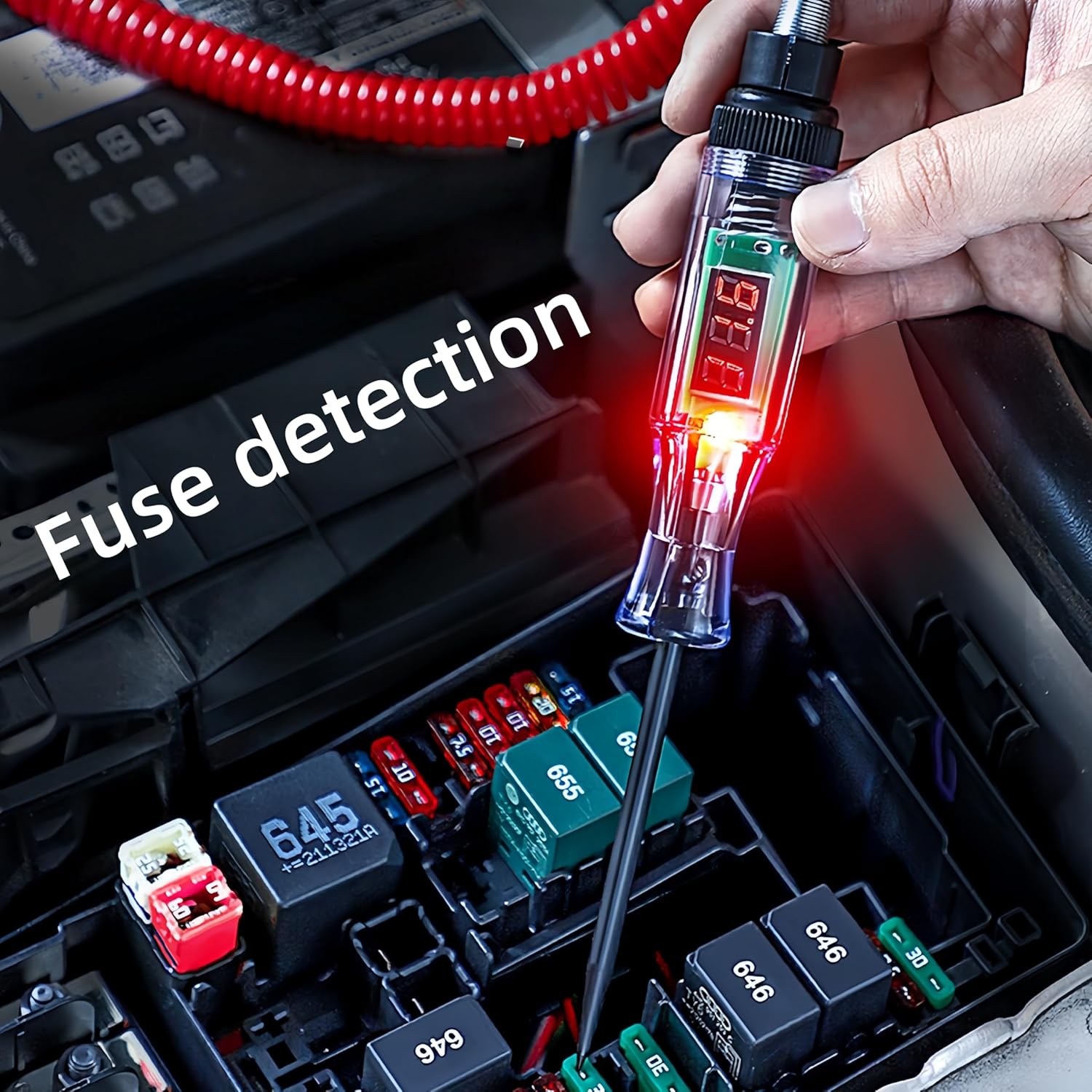
Figure 5.1: The circuit tester in use, demonstrating fuse detection within a vehicle's fuse box.
Video 5.1: Demonstration of DC voltage testing and resistance testing using a similar automotive circuit tester. Note: The voltage range shown in this video may differ from the 5-90V range of this product.
Video 5.2: Demonstration of voltage testing and continuity testing with an automotive test light. Note: The voltage range shown in this video may differ from the 5-90V range of this product.
5.2. Δοκιμή συνέχειας
- Ensure the circuit is de-energized before performing continuity tests.
- Connect the alligator clip to one end of the component or wire to be tested.
- Touch the probe tip to the other end.
- If continuity exists, the LED indicator will light up (typically green for continuity, or red if connected to a positive source through the component) and the display may show a low resistance value or a specific continuity symbol.
Video 5.3: Demonstration of polarity detection and continuity testing using a power circuit probe tester. Note: The voltage range shown in this video may differ from the 5-90V range of this product.
5.3. Fuse Testing
- With the circuit energized, connect the alligator clip to a known good ground.
- Touch the probe tip to each test point on the top of the fuse.
- If both sides of the fuse show a voltage reading, the fuse is good. If one side shows voltage and the other does not, the fuse is blown.

Figure 5.2: The Automotive Circuit Tester is suitable for use with motorcycles, heavy equipment, trucks, and cars.
6. Συντήρηση
- Καθάρισμα: Σκουπίστε το δοκιμαστικό μηχάνημα με ένα καθαρό, στεγνό πανί μετά από κάθε χρήση. Μην χρησιμοποιείτε λειαντικά καθαριστικά ή διαλύτες.
- Αποθήκευση: Store the tester in a dry, cool place, away from direct sunlight and extreme temperatures. Always replace the protective probe cover before storage.
- Επιθεώρηση καλωδίου: Regularly inspect the spring wire and alligator clip for any signs of damage, fraying, or corrosion. Replace if necessary.
7. Αντιμετώπιση Προβλημάτων
| Πρόβλημα | Πιθανή αιτία | Διάλυμα |
|---|---|---|
| No display/LED light | Poor ground connection; No power in circuit; Faulty tester. | Ensure alligator clip has a solid ground. Verify circuit has power. Test tester on a known live circuit. |
| Ανακριβής τόμtagδιάβασμα | Poor connection; High resistance in circuit. | Clean connection points. Ensure firm contact with probe. |
| "H" or error message on display | Τομtage exceeds 90V DC. | Immediately disconnect the tester. This tester is not designed for voltages πάνω από 90V DC. |
8. Προδιαγραφές
| Χαρακτηριστικό | Λεπτομέρεια |
|---|---|
| Αριθμός μοντέλου | 605195370602 (DYB-002) |
| Τομtagε Εύρος | 5-90V DC |
| Τύπος οθόνης | Ψηφιακό LED |
| Υλικό ανίχνευσης | Ανοξείδωτο ατσάλι |
| Τύπος καλωδίου | Extended Spring Wire |
| Μήκος καλωδίου | Περίπου 96 ίντσες (244 εκ.) |
| Διαστάσεις προϊόντος (Μ x Π x Υ) | 18.42 x 2.01 x 2.01 cm (7.25 x 0.79 x 0.79 ίντσες) |
| Βάρος αντικειμένου | 90 γρ |
| Πηγή ισχύος | Powered by circuit under test |
| Κατασκευαστής | JINJIANG |
| Πιστοποιήσεις | CE, ETL |
9. Εγγύηση και υποστήριξη
Για πληροφορίες σχετικά με την εγγύηση ή την τεχνική υποστήριξη, απευθυνθείτε στον αντιπρόσωπο λιανικής πώλησης ή στον επίσημο αντιπρόσωπο του κατασκευαστή. webτοποθεσία. Κρατήστε την απόδειξη αγοράς για αξιώσεις εγγύησης.